
David Marlowe • Owner/CEO • DMAR Technical Training and DMAR Business Centers USA
The fluid level in a hydraulic and lube oil system reservoir is often overlooked—and taken for granted. Fluid flow is the action in the hydraulic system that transfers the energy to perform the work. In addition, the fluid flow cools system components, lubricates sliding and rotating surfaces in the system components and removes contaminants from the system, all while sealing running clearances to minimize internal leakage.
Since fluid flow starts and ends at the reservoir, we must first understand the differences in the reservoirs used in a hydraulic system as compared to a lube oil system. In both systems, reservoir size is the key to operating an efficient system, by providing a steady supply of fluid, acting as a de-aerator and allowing the entrained air to rise and escape while solid contaminants settle to the bottom of the reservoir. This also makes it a fluid conditioner while providing a mounting platform for the pump(s).
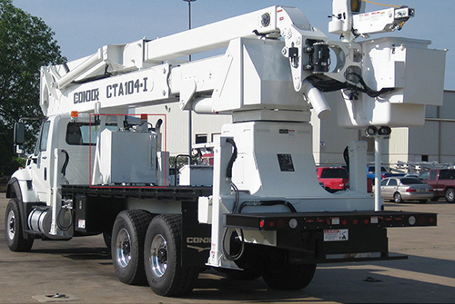
The 109-gal capacity hydraulic oil reservoir (boxed in red) is fabricated by The IFH Group from aluminized steel and is used in an aerial work platform bucket truck. Hydraulic fluid reservoirs are much smaller than lubrication reservoirs, which can be sized for thousands of gallons.
Lube oil system reservoir: The volume of the oil reservoir should take into consideration the total feed to all bearings, gears, controls and other machine elements multiplied by the oil dwell time. For instance, allowing a 5-min dwell time for separation of entrained air and contaminants, a 1,000-gpm oil feed to bearings for a turbine-generator would call for a 5,000-gal reservoir.
Sizing the piping in the lube oil system: Pipe diameter must be large enough to avoid undue pressure drop in feed lines, to avoid backup in drain lines at the minimum oil temperature and to avoid cavitation in pump suction lines. Feed lines usually operate at 5 to 10 ft/sec velocity, drain lines 0.5 to 1.0 ft/sec and pump suction lines 3 to 5 ft/sec.
Hydraulic system reservoir: Sizing a hydraulic reservoir suggests that its volume (rule-of-thumb) should equal three times the rated output of the system’s fixed-displacement pump or mean flow rate of its variable-displacement pump. This means a system using a 7-gpm pump should have a 35-gal reservoir. However, the substantial heat that can be generated within a hydraulic system should be considered when selecting the reservoir size. For example, large accumulators or cylinders that use large volumes of fluid or systems exposed to high ambient temperatures may require a larger reservoir unless they incorporate a heat exchanger.
Sizing the piping in a hydraulic system: The proper line size selection in the hydraulic system is critical to get maximum performance and life from the hydraulic system components.
The four basic line types in a hydraulic system are:
1. Pump suction
2. Return (Low pressure <100 psi)
3. Medium pressure (500 to 2,000 psi)
4. High pressure (2,100 to 5,000 psi) (Undersizing fluid lines will result in high-pressure losses and cause system overheating.)
Lines should be sized as follows:
• Suction: 2 to 4 ft/sec
• Return: 10 to 15 ft/sec
• Medium pressure: 15 to 20 ft/sec
• High pressure: 20 to 25 ft/sec
Oversizing lines increases the cost of the system.
Velocity through a line can be calculated with the formula: Velocity (ft/sec) = gpm x 0.3288/Area
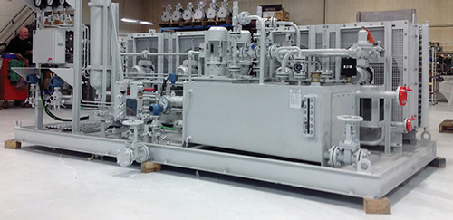
This lubricating oil system for the oil and gas industry is much larger and complex than a hydraulic fluid reservoir. Photo courtesy of RHM Flodraulic Group
On extremely long lines, the pressure drop through the pressure and return lines must be accounted for. This helps to ensure sufficient pressure is available at the actuator.
The proper level in the reservoir ensures adequate space above the fluid level to give off trapped heat and non-condensable gases while reducing return line head pressure, allowing the fluid returning to flow at the proper feet per second.
The proper level in the reservoir also ensures that the Net Positive Suction Pressure Available is greater than the Net Positive Suction Pressure Required by the pump, regardless if the pump is a dynamic or positive displacement pump. This ensures that the fluid flowing through the pump suction line is at the recommended feet per second. By maintaining a laminar fluid flow, energy loss through heat in the piping is lowered and the possibility of cavitation in the pump and discharge piping is greatly reduced.
Improper fluid levels in the reservoir will not only affect the overall efficiency of system operation; the increased or decreased velocities can cause system component damage leading to extended down time and expensive repairs.
Filed Under: Fluid Power World Magazine Articles