Fluid Power World

  • Home
  • Technologies
    • Hydraulics
      • Cylinders & Actuators
      • Filtration/Contamination Control
      • Fittings, Couplings & Adapters
      • Fluids
      • Fluid Conditioning
      • Hose & Tubing
      • Pumps & Motors
      • Related Technologies
      • Sealing
      • Sensors & Gauges
      • Valves & Manifolds
    • Pneumatics
      • Air Preparation & Regulation
      • Compressed Air Technologies
      • Cylinders & Actuators
      • End Effectors & Grippers
      • Fittings, Couplings & Adapters
      • Hose & Tubing
      • Sensors
      • Vacuum
      • Valves & Manifolds
  • Engineering Basics
  • Trending
  • Resources
    • Digital Issues
    • Pneumatics Tech Toolbox
    • Podcasts
    • Subscribe to Fluid Power World Print Magazine
    • Videos
    • Webinars / Digital Events
    • White Papers
  • Women in Engineering
    • Women in Fluid Power
    • Women in Engineering
  • Design Guide Library
  • Classrooms
    • Pneumatics Classroom
  • SUBSCRIBE

What is the flow coefficient Cv?

By Ken Korane | January 28, 2019

Share

In the pneumatic industry, Cv is one standard for expressing the flow capacity of devices used in pneumatic systems. However, there are multiple other standards that also express flow capacity, including effective orifice size and normal liters per minute, as well as measurements of actual flow rates at specific pressure differentials. These methods are not interchangeable and even have different meanings, interpretations, and formulas from one manufacturer to another. Therefore, it is important that engineers have a solid understanding of the available data to prevent components from being oversized or undersized in pneumatic systems.

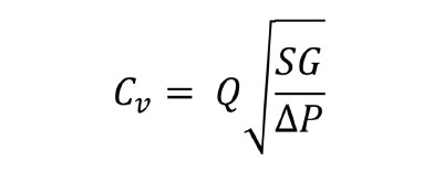
This is the basic equation for Cv, where Q is the rate of flow (gallons per minute), SG is the specific gravity of the fluid, and P is the pressure drop across the valve (psi).

It is commonly understood that nearly every pneumatic device creates a flow restriction in the system. Cv — the coefficient of flow — is one standard for expressing the flow capacity of devices used in a pneumatic system.

Many manufacturers around the world have adopted Cv as the standard value to express the flow capacity of their components. Cv is based on the volume flow rate of water at 60°F through a device within one minute at a 1 psi differential. However, there is a problem with using this equation in pneumatic applications.

Because air is compressible, Cv must have additional factors built into the equations to compensate for that compressibility. For pneumatic applications, Cv should be calculated by referencing the appropriate equation and conditions outlined in the ANSI/NFPA T3.21.3 specification. When doing so, it is important to observe proper test conditions. This includes ensuring that pressure upstream of the component being tested is a nominal 95 psia, and that the differential between the upstream and downstream pressure of the component being tested is 1 psi.

This example shows how one manufacturer deviates from the ANSI/NFPA standard with their Cv calculation. Here, Q is the rate of flow (standard cubic feet per hour), ΔP is the pressure drop across the valve (psi), P1 is the inlet pressure (psia), P2 is the outlet pressure (psia), SG is the specific gravity of the fluid at standard atmospheric pressure (60°F and 14.7 psia), T is the absolute temperature Rankine (°F + 460).

It is important to note that not every manufacturer expresses the flow capacity of their valves as Cv based on the ANSI/NFPA specification. For example, the nearby equation is the calculation used by one manufacturer. The constant in the equation accounts for the difference in the specific gravity of air versus the specific gravity of water. This calculation does not follow the pressure requirements of the ANSI/NFPA specification.

While the Cv method is the most popular standard, its accuracy relies on manufacturers adhering to the same test procedures. Some manufacturers test and publish Cv without any explanation of how they produce the values, while others publish explanations but fail to follow the ANSI/NFPA T3.21.3 standard.

Because Cv only looks at a 1 psi differential, the calculated flow at low pressures can be very accurate, but certain applications that have higher differentials can produce flows that do not match the calculated results. It is important to be aware that misinterpreting the Cv value can lead to differences in ratings of over 20%.

Information for this story provided by Mike Kettering, Technical Sales Specialist at Clippard Instrument Laboratory.


Filed Under: Pneumatic Tips
Tagged With: clippard, Clippard Instrument Laboratory
 

Current Digital Issue

  Easier access to more of our content Every other month, readers of Fluid Power World have access to our beautiful print and digital editions, where we share a selection of the best fundamentals content, technology news, case studies, and technical articles that cover the gamut of hydraulics and pneumatics system design. But we only…

Subscribe!

Fluid Power World is written by engineers for engineers engaged in designing machines and or equipment in Off-Highway, Oil & Gas, Mining, Packaging, Industrial Applications, Agriculture, Construction, Forestry, Medical and Material Handling. Fluid Power World covers pneumatics, mobile hydraulics and industrial hydraulics.

Fluid Power Design Guides

fluid
“fpw
EXPAND YOUR KNOWLEDGE AND STAY CONNECTED
Get the latest info on technologies, tools and strategies for Fluid Power Professionals.

RSS Featured White Papers

  • Moving fluid power forward
  • High-force linear motion: How to convert from hydraulic cylinders to electric actuators and why.
  • A technical comparison: Performance of pneumatic cylinders and electric rod actuators
Fluid Power World
  • Hose Assembly Tips
  • Mobile Hydraulic Tips
  • Pneumatic Tips
  • Sealing & Contamination Control Tips
  • About us
  • Contact Us

Copyright © 2024 WTWH Media LLC. All Rights Reserved. The material on this site may not be reproduced, distributed, transmitted, cached or otherwise used, except with the prior written permission of WTWH Media
Privacy Policy | Advertising | About Us

Search Fluid Power World

  • Home
  • Technologies
    • Hydraulics
      • Cylinders & Actuators
      • Filtration/Contamination Control
      • Fittings, Couplings & Adapters
      • Fluids
      • Fluid Conditioning
      • Hose & Tubing
      • Pumps & Motors
      • Related Technologies
      • Sealing
      • Sensors & Gauges
      • Valves & Manifolds
    • Pneumatics
      • Air Preparation & Regulation
      • Compressed Air Technologies
      • Cylinders & Actuators
      • End Effectors & Grippers
      • Fittings, Couplings & Adapters
      • Hose & Tubing
      • Sensors
      • Vacuum
      • Valves & Manifolds
  • Engineering Basics
  • Trending
  • Resources
    • Digital Issues
    • Pneumatics Tech Toolbox
    • Podcasts
    • Subscribe to Fluid Power World Print Magazine
    • Videos
    • Webinars / Digital Events
    • White Papers
  • Women in Engineering
    • Women in Fluid Power
    • Women in Engineering
  • Design Guide Library
  • Classrooms
    • Pneumatics Classroom
  • SUBSCRIBE